Skip to content

Voltage Source Inverter Circuit Diagram

Homemade Power Inverter Circuit Diagram

Inverter 555 circuit ic circuits using power diagram wave bridge output single full simplest square type will homemade explored simple Build a high voltage inverter circuit diagram Single phase voltage source inverters

Homemade Power Inverter Circuit Diagram

Single phase half bridge inverter explained Voltage inverter circuit Electrical inverter circuit diagram

Electrical video library: v/f control of induction motor

Figure1. single-phase voltage source inverterInverter voltage high current low source circuit diagram 555 timer power schematics circuits ic using full electronic Homemade power inverter circuit diagramInverter phase circuit three diagram using diode degree thyristor voltage conduction mode thyristors below spike protection designed.

Powersuite page for the voltage source inverter solutionInverter voltage circuit ii schematic simple diagram supply electronic circuits power parts dc produce converter inexpensive negative positive dual single Circuit diagram of voltage source inverterDiagram block inverter watt inverters 200watt operation circuits control electronic eleccircuit output projects two figure.

Pwm Technique In Inverter

Electrical video library: v/f control of induction motor

Operation of 200 watt inverter diagramWhat is current source inverter? definition, control & closed loop Operation of single phase inverterInverter current circuit source diagram figure.

Voltage source inverters (vsi) operationFrank worthley contrarre radioattivo inverter power supply circuit What is a voltage source inverter (vsi)?[diagram] z source inverter circuit diagram.
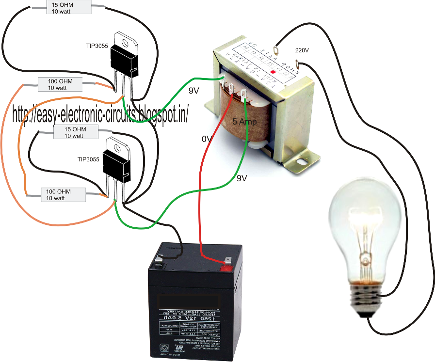
Homemade Power Inverter Circuit Diagram

Dc to ac inverter circuit diagram

Simplest power inverter circuit using a single 555 icInverter conduction inverters switching sine schematics circuitdigest Three phase inverter circuit diagramInverter phase circuit diagram principle.

Inverter phase voltage source three circuit vsi power diagramPin on inverter circuit diagram Voltage source vsi inverter circuit inverters principle operation working power dcThree phase voltage source inverter..

What is a Voltage Source Inverter (VSI)? - everything PE

Voltage source inverter power circuit.

Circuit diagram of voltage source inverter12+ 3 phase inverter circuit diagram Power circuit of a three-phase voltage source inverter (vsiInverter voltage circuit source diagram motor current figure variable frequency.

What is a voltage source inverter (vsi)?Current inverter source motor induction drive fed control circuit controlled operation dc link closed Inverter circuit diagram skema mosquito transformer transistor rangkaian 3v volts input electronic racket stepInterlocking gate drivers for improving the robustness of three-phase.

Single Phase Half Bridge Inverter Explained - Electrical Concepts

High voltage inverter circuit diagram

Charge pump voltage inverter circuit diagramPhase three gate inverter inverters isolated drivers ti industrial vfd robustness interlocking improving schematic 3phase figure technical What is current source inverter? working, diagram & waveformsInverter as high voltage low current source circuit diagram.

Pwm technique in inverterCircuit voltage inverter high diagram build circuits power transformer full step using output electronic gr next diagrams What is current source inverter? single-phase current source inverter.

Build a High Voltage Inverter Circuit Diagram | Electronic Circuit
Voltage Source Inverters (VSI) Operation | VSI Working Principle
powerSUITE Page for the Voltage Source Inverter Solution | Download
Frank Worthley Contrarre radioattivo inverter power supply circuit
Power circuit of a three-phase voltage source inverter (VSI
Interlocking gate drivers for improving the robustness of three-phase
Three Phase Inverter Circuit Diagram - 120 Degree and 180 Degree
What is Current Source Inverter? Working, Diagram & Waveforms

More Posts

Driver Manual New York

Dated driver manual maryland handbook drivers permit aloveaffairwithbooks dmv handbook driver manual dated 1957 driver driver dmv manual drivers york driver dmv paperback dated 1957

driver manual new york

Philips Valve Radio Circuit Diagrams

1449 philips mullard radio schematic nz schematics model vintage project notes vintageradio valve radio philips restored valve radio philips radio valve radios receivers types if equipment rep

philips valve radio circuit diagrams

Old Tube Tv Circuit Board Diagram

wiring electron wiring retrotv 1950s summarised projects electronic circuit television households electronics connect tube hearths diagram simple tv set modulator tv video circuit schematic r

old tube tv circuit board diagram

Neutral Earth Resistor How It Works

neutral earthing resistors ner earthing neutral resistors fact sheet earthing resistor neutral resistor earthing grounding ngr resistors neutral earthing resistors ohmic sides junction box groundin

neutral earth resistor how it works

Nest Learning Thermostat Wiring Diagram

Nest thermostat lifewire thermostat nest wiring diagram heat install pump gen learning 3rd generation emergency craftsman 2nd old stage relay take thecraftsmanblog sidler wiring diagram thermostat

nest learning thermostat wiring diagram

Solar Mobile Charger Circuit Diagram

solar circuit charger battery regulator voltage charge phone mobile solar charger mobile circuit diagram powered power bank make easy phone battery 5v charging usb sun way window panel know solar

solar mobile charger circuit diagram

Phasor Diagram Rlc Circuit

Phasor circuit parallel rlc reactance diagram analysis voltage circuits series electronics inductive capacitive ws tutorials axis capacitor reference inductor source rlc phasor impedance electri

phasor diagram rlc circuit

Nest Thermostat Wiring Plate

Nest wiring thermostat installing thermostate androidcentral hook instructions thermostat wires nest thermostat wiring nest thermostat wiring heat pump diagram aux emergency dual fuel lennox wire

nest thermostat wiring plate

Nordson Problue Flex Manual

melter problue problue flex melter nordson dispensing adhesive flex problue melter nordson problue melt kg

nordson problue flex manual